

Background: In robotics class (MECE 404) the teacher divided the class into teams of two with the very open ended assignment of: build a robot. My teammate Charlotte and I spent a week brainstorming ideas. After looking around the robotics lab one day we noticed a big bin of unsorted resistors, as many robotics/electronics labs have, and decided to build a robot to sort that bin.
Task 1
Determine sorting method: The first task was to design the overall look of the robot. While I would like to show all of the different option here those have been lost with time. What was decided on was a robot that would drive along a track with bins below it. After reading the resistance the robot would drive to the appropriate bin and drop the resistor.
Some other disregarded concepts where: having bins in a circular manner with a central hopper. A resistor would be dispensed and the shoot would be aligned to the appropriate bin. The biggest problem was you’re limited to a certain number of sortable resistors thats dependent on the number of bins which fit around a ring. Another concept was to have a conveyor with arms to push resistors off into bins below.
At this point it was also decided the main frame of the robot would be made from erector parts, and be controlled with an Arduino Uno
Task 2
Hopper/Feeder: There are a lot of hopper feeder methods used in industry. The hopper chosen for this project was a simple triangle shape that funneled resistors down to a column one resistor wide. To receive the resistor a drum was 3D printed which featured a slot deep enough for one resistor at a time. The slot aligns with the hopper outlet, picks up a resistor and then rotates to deposit it to the measuring leads. The hopper had to be placed precisely above the drum so that resistors couldn’t leak out.
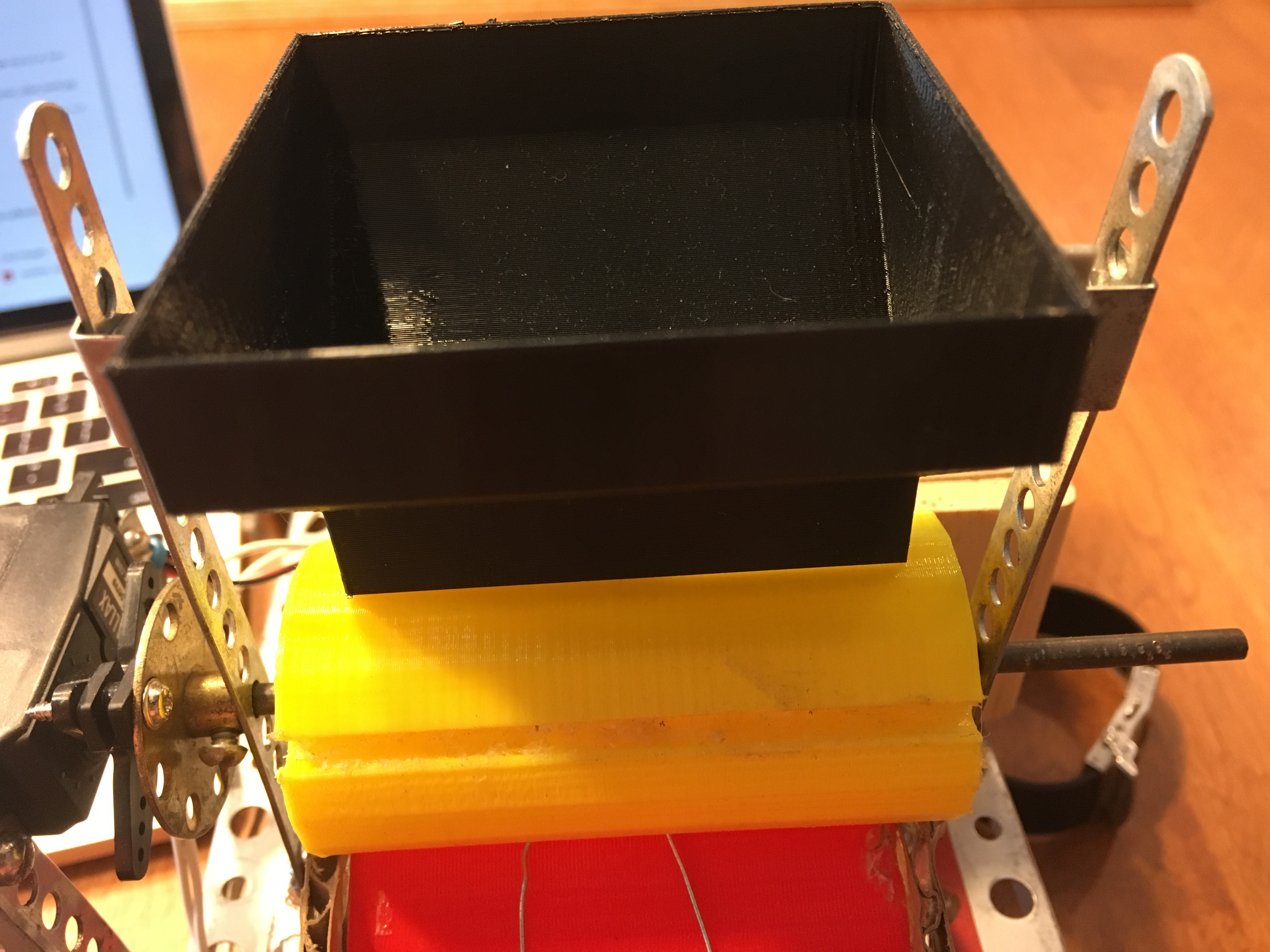
Hopper/Feeder: There are a lot of hopper feeder methods used in industry. The hopper chosen for this project was a simple triangle shape that funneled resistors down to a column one resistor wide. To receive the resistor a drum was 3D printed which featured a slot deep enough for one resistor at a time. The slot aligns with the hopper outlet, picks up a resistor and then rotates to deposit it to the measuring leads. The hopper had to be placed precisely above the drum so that resistors couldn’t leak out.

This method worked well if the leads were straightened before being fed into the hopper. Occasionally the drum would get jammed but with better manufacturing and alignment tolerances much of that can be solved. The other issue was occasionally the drum fails to pick up a resistor. However, after 2-3 tries its able to get one, and this is something the code accounts for.
Task 3
How to determine resistance: When dealing with resistors there’s really two ways of determining resistance.
- Read the color bands to determine the resistance
- Measure the resistance
While there are techniques to have cameras read resistor bands and then use image technology to determine the color bands all of the papers describing this technique made it sound HARD. So Charlotte and I decided to go with the easier method of measuring the resistance.

The resistance was measured by dropping a resistor onto two metal leads attached to a tray as shown on the left. One of the leads was hooked up to the 5 V supply pin on the Arduino and the other was hooked up to an analog input pin to measure the voltage drop. Using ohms law the total resistance could be calculated.
There’s a catch, without a second resistor in series the voltage drop will always be 5 volts. To fix this a second resistor is hooked up in series to the analog input. One final problem was determined, which was the resistors had to be in the same order of magnitude. If the known resistor is 1M ohm, the one being measured can’t be 1 ohm because it is so insignificant. Therefore 3 resistor where used and the user had to select which range to sort in.
- 22-10k ohms
- 400-100k ohms
- 10k-1M ohms
In order for this to work successfully the Arduino had to wait a few seconds for the resistor to settle before taking the measurement.
Task 4
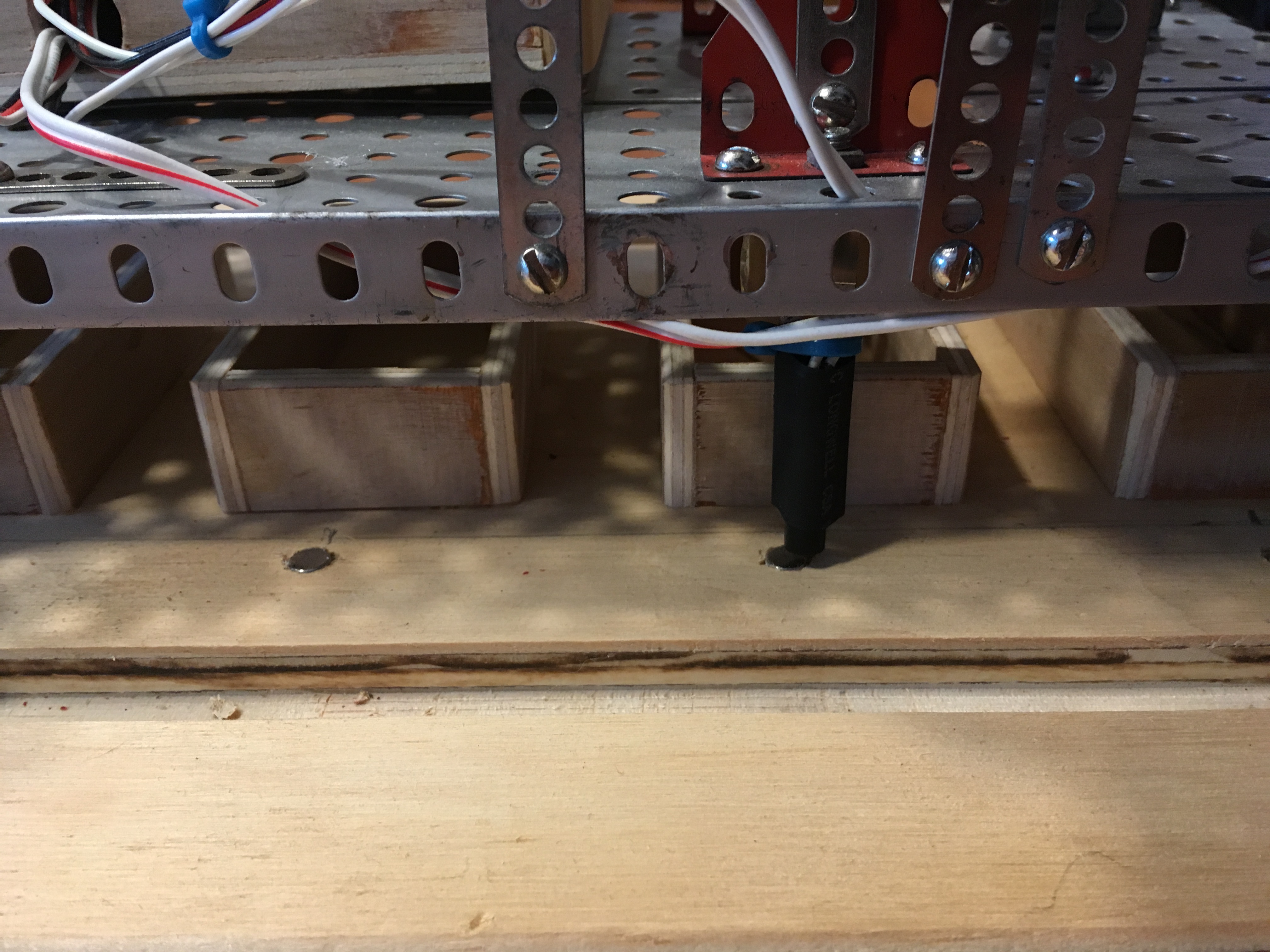
Determining Robot Location/Bins: For the proof of concept the robot track was outfitted with 5 bins. 4 were for 4 different resistor values determined by the user and the fifth is “everything else”. In order to determine the robots location relative to the bins the board the robot had a read switch on it. On the board were neodymium magnets. So the robot would keep track of how many boxes it had passed. The only issue with this method was overshoot. To fix this the resistor dropper was slightly modified and the driving speed was slowed down a bit.
Final Product
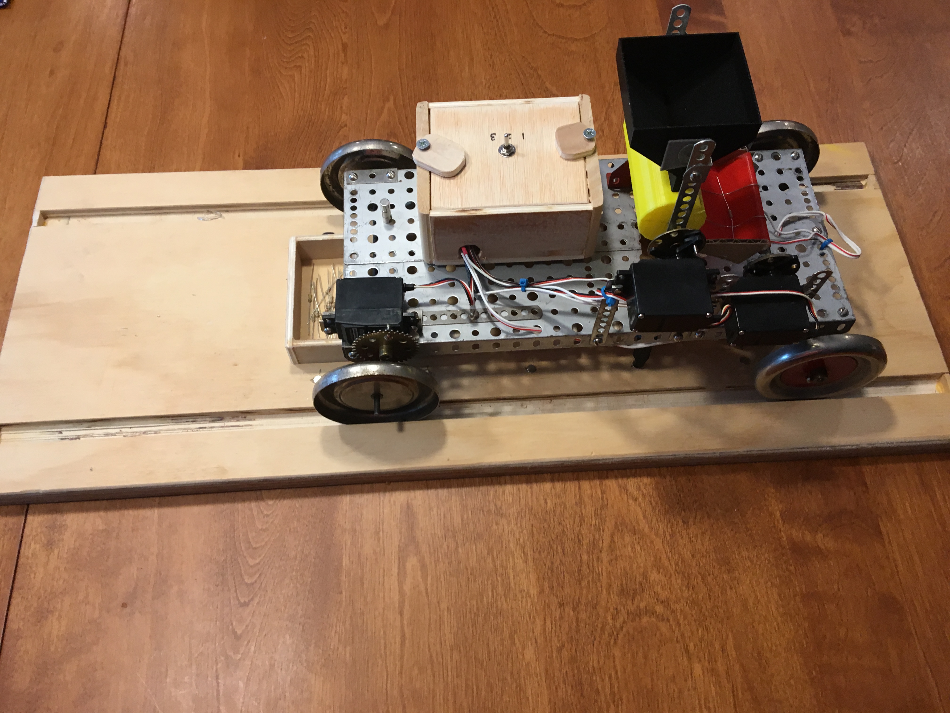
The robot was able to meet all of our design criteria. The hopper was able to hold 30+ resistors (estimated to hold 100+). Could correctly determine resistance and was able to correctly sort resistors 80% of the time.
Date: Fall 2017
